Abstract - A commercially available complete microprocessor controlled, fully automated 10 Volt Josephson voltage standard system operated with a cryocooler was developed in cooperation between IPHT and Supracon. The system operates with an array of altogether 19,700 SIS Josephson tunnel junctions. A direct comparison to a helium-based system showed an agreement of 1.3 nV at a relative uncertainty of 2x10⁻¹⁰.
Received and accepted April 1, 2011. Reference No. ST254; Category 4. This paper is to be presented at the QM 2011 Conference and will be published in the Polish journal “Elektronika” No. 6 (2011); we pre-publish with permission.
I. INTRODUCTION
Josephson voltage standard systems based on arrays of SIS tunnel junctions are commonly used as primary DC voltage standards. Applying them, secondary voltage standards as well as high precision digital voltmeters can be calibrated with the highest level of accuracy. Further developments are focused on a cryogenic-free operation
[1, 2] and on programmable Josephson arrays
[3, 4]. Because programmable Josephson arrays are difficult to manufacture at the 10 V level, and in addition require expensive control electronics, the SIS Josephson voltage standard systems are still attractive, in particular due to the advantage of the availability of zero current steps.
The system was developed to be easy to use and to avoid a manual control of the Shapiro steps. In the following we describe the performance of the fully automated 10 Volt Josephson voltage standard system “supraVOLT-control” suitable for all DC voltage calibrations.
II. SETUP OF THE SYSTEM
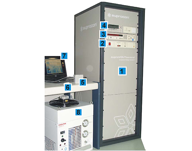
The Josephson voltage standard system “supraVOLT-control” in the cryocooler version is shown in
Figure 1. A pulse tube cooler delivered from Transmit GmbH, Giessen, was used to establish the chip operating temperature of about 4K. The cryocooler itself produces a cooling power of about 180mW at the cold stage. To reduce the thermal heat to the cold stage a 75 GHz dielectric microwave waveguide
[2] were used for microwave transmission. The first and second stage of the cryocooler are thermally shielded and placed in a vacuum chamber. The chip itself is magnetically shielded by a cryoperm tube. This protection is required against earth magnetic field and the disturbances issued from the magnetic phase transition of the material located in the regenerator of the cryocooler. A box including LC filters was installed on the top of the cryocooler to reduce the noise level introduced by the bias electronics and the device under test. Careful grounding was necessary to reduce additional electrical noise from the compressor unit. A good thermal coupling of the JJA chip to the cold stage is important in order to avoid a chip overheating. A thermal interface balances the different thermal expansion coefficients of the copper cold finger and the silicon chip.
Standard 4 K cryocoolers show temperature oscillations of about 0.2 K at the compressor cycling frequency. By the use of a nickel erbium plate, a material with a relative high thermal capacity at 4 K, the temperature oscillation could be reduced to 5 mK resulting in a stable operation.
Fig. 1. Photograph of the cryocooler-based Josephson voltage standard system “supraVOLTcontrol” including the following components: 1: Pulse tube cooler with a SIS Josephson junction array and the 75 GHz microwave electronics installed in the 19” rack, 2: Control electronics, 3: EIP 578B source locking counter, 4: Keithley 2182A nanovoltmeter, 5: 3-channel polarity reversal switch, 6: Sensors for temperature, pressure and humidity, 7: Laptop, 8: compressor unit with an input power of 2.5 kW.
The microwave with a frequency of 75 GHz is provided by a Gunn oscillator which is stabilized via the PLL of a 578B EIP counter. The microwave power is adjusted automatically to its optimum by a voltage controlled attenuator depending on the required Josephson output voltage.
The Josephson junction array (JJA)
[5] is controlled by a μController electronics. A current source drives an AC current through the JJA and in parallel two 16 bit DACs as a voltage source adjust a course and fine voltage. In series to the voltage source a 100 Ω resistor is used for the step selection. With increasing microwave power Shapiro steps appear with a step number given by the voltage of the DACs and the resistor characteristic. The operating point of the JJA is found when the voltage drop at the resistor becomes constant (± 100μV). The difference voltage of the JJA and a connected voltage standard is read out by a Keithley 2182A which acts as a null detector. In general the chosen voltage difference is smaller then 240 μV and 1 μV in the case of a direct comparison, respectively. A small difference voltage ensures a marginal influence of the gain error of the null detector. The JJA is disconnected from the bias electronics as well as from ground during the readout of the null detector.
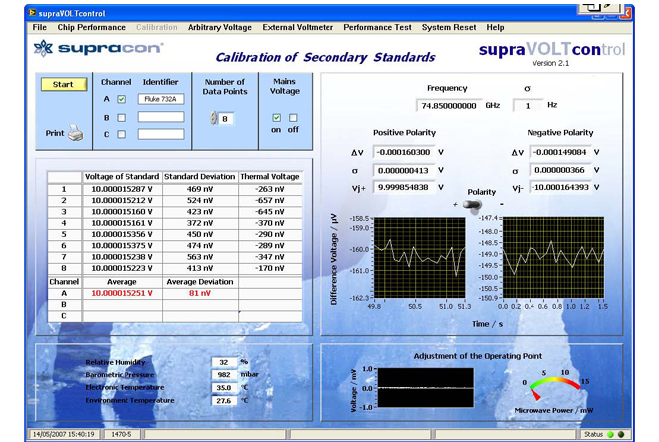
Fig. 2. Graphic user interface for calibration of a Fluke 734A secondary voltage standard at 10 V. The calibration procedure is fully automatic. Therefore, the Josephson voltage steps are selected and checked by microprocessor control of the current, voltage and microwave power. The difference in voltage between the secondary voltage standard and the Josephson circuit is measured and shown for both polarities and the resulting calibration voltage is displayed. In the picture eight measurements are shown and their average is displayed along with their standard deviation.
The system can automatically calibrate secondary voltage standards as well as the most common digital voltmeters, in a fast and highly accurate manner. For example the typical time for the calibrating a Fluke 732A with 20 points each in plus and minus polarity is only 30 s. For the measured DVMs the gain factor and nonlinearity will be specified.
The typical software user interface for calibrating a Fluke 732A with the measurement results are shown in Figure 2. Altogether 8 data points were measured with their standard deviation and the offset voltages in the wiring loop. Each data point consists of 20 readings of the voltage difference between the Fluke voltage and the Josephson voltage read out by the integrated nanovoltmeter in plus and minus polarity. The driving frequency is displayed with their standard deviation and the data of the integrated sensors for environment temperature, barometric pressure and humidity. The calculated output voltages of the Fluke 732A are displayed on the end of the table with its standard deviation.
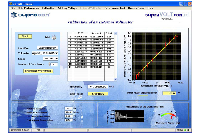
External voltmeters can be calibrated automatically as well. The software user interface and the measurement results are displayed in Figure 3. As an example an Agilent 34420A is tested and read out via the GPIB interface. Eleven data points were measured in the 100 mV range. The Josephson voltages and the mean of the readings of the external voltmeter with their standard deviation of the mean are displayed. The diagram shows the linear gain error of the investigated external voltmeter. The y-axis represents the difference between the readings of the external voltmeter to the real Josephson voltage in dependence of the adjusted Josephson voltage. With the knowledge of the gain factor you can improve the measurement accuracy of the external voltmeter by taken this factor into account. The measured root mean square error represents the nonlinearity of the voltmeter.
Fig. 3. Graphic user interface for calibration of external voltmeters, for example a Agilent 34420A. The calibration of the external voltmeter is fully automatic. You can choose the voltage range of the voltmeter and the number of data points. The voltmeter data are read out via IEEE GPIB. The calculated gain factor and the deviation of the linearity are displayed.
III. DIRECT COMPARISON
A direct comparison between the cryocooler based system to a Liquid helium based system was carried out at a voltage level of 10 V in order to verify their accuracy. One system, called S1, provided the Josephson voltage at 10 V, and the second system S2 measured this voltage. Both systems were driven at the same frequency of 74.7 GHz stabilized and phase locked to a GPS synchronized 10 MHz reference frequency. In order to avoid unwanted interferences of the systems during adjustment the Shapiro steps only one JJA was connected to its bias electronics and to ground, the other JJA was floating.
The procedure was started with the adjustment of a Shapiro step at 10 V with system S1. Its step voltage is always measured by the Keithley 2182A of S1 from which value the absolute Josephson voltage was calculated. Afterwards the system S2 was connected to its bias electronics and a Shaprio step near 10 V was chosen, too. The Keithley 2182A of system S2 was used as null detector and measured the difference voltage of both systems. System S2 was searching a Josephson voltage with the same step number as S1 in order to minimize the voltage difference and thereby the gain error effect of the null detector. The null detector read out 20 points with 20 ms integration time and no filters. It is important to note, that during this time both systems were floating from the ground, and they were not connected to their bias electronics. During connection and disconnection of the systems it could happen that the Josephson voltage of S1 jumps to a neighboring step, but if the difference to 10 V was smaller than 1 mV, the comparison was continued at this level. During adjustments of the Josephson voltages the null detector is shorted in order to avoid an offset shift.
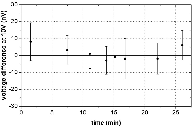
Fig. 4. Measurements of the direct comparison between a cryocooler-based and a liquid-helium-based Josephson voltage standard system at a voltage level of 10 V. The difference of the voltages was UPTCS - ULHeS = 1.3 nV with a combined standard measurement uncertainty of 2 nV.
The thermal voltages in the wires of both systems were eliminated by repeating the procedure at minus polarity by a reversal of the output voltages. The thermal EMF and offset voltages were about 200 nV. The polarity reversal switch was always in the same position during the measurements.
The results of the direct comparison are shown in Figure 4. Altogether eight measurements were made in about ten minutes. The error bars denote the standard deviation of the mean value of a single plus-minus-measurement with 20 points for each polarity. The result of the direct comparison is a difference of 1.3 nV at 10 V.
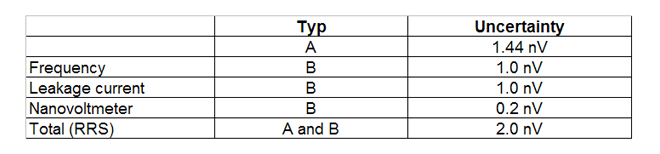
The combined standard uncertainty includes type A and type B components from both Josephson systems and are listed in Table I. The experiments demonstrate an accuracy of the supraVOLTcontrol systems better than 2×10⁻¹⁰.
Table I. Estimated uncertainty components for the direct comparison at 10 Volt.
ACKNOWLEDGMENT
Many thank to R. Behr from the Physikalisch-Technische-Bundesanstalt (PTB), Braunschweig for helpful discussions and to G. Thummes for his assistance in providing and installing the cryocooler.
REFERENCES
[1] Y.-H. Tang, R.T. Hunt, R. Robertazzi, et al., “Cryocooled Primary Voltage Standard System,” IEEE Trans. Instrum. Meas. 46, 256-259 (1997).
[2] G. Wende, M. Schubert, T. May et al.,, “Josephson Voltage Standard Circuit Operation with a Pulse Tube Cooler,” IEEE Trans. Appl. Supercond. 13, 915-918 (2003).
[3] C. A. Hamilton, S. P. Benz, C. J. Burroughs, and T. E. Harvey, “SNS Programmable Voltage Standard”, IEEE Trans. Appl. Supercond. 7, 2472-2475 (1997).
[4] R. Behr, L. Palafox, G. Ramm, H. Moser, J. Melcher “Direct comparison of Josephson waveforms using an AC quantum voltmeter”, IEEE Trans. Instrum. Meas. 56, 235-238 (2007).
[5] M. Schubert, T. May, G. Wende, L. Fritzsch, and H.-G. Meyer, “Coplanar strips for Josephson voltage standard circuits”, Appl. Phys. Lett. 79, 1009-1011 (2001).
« back
Contact us
Supracon AG
An der Lehmgrube 11
07751 Jena
Germany
Tel.: +49-3641-2328100
Fax.: +49-3641-2328109
info(at)supracon.com